Methods to design the cooling and dehumidifying coil either chilled water coil or Dx evaporator coil are usually based on log mean enthalpy or log equivalent dry-bulb temperature difference 1. All evaporator coils are counter flow circuited and equipped with pressure type distributors and all distributor tubes are of equal length to assure equal distribution of refrigerant to each circuit.
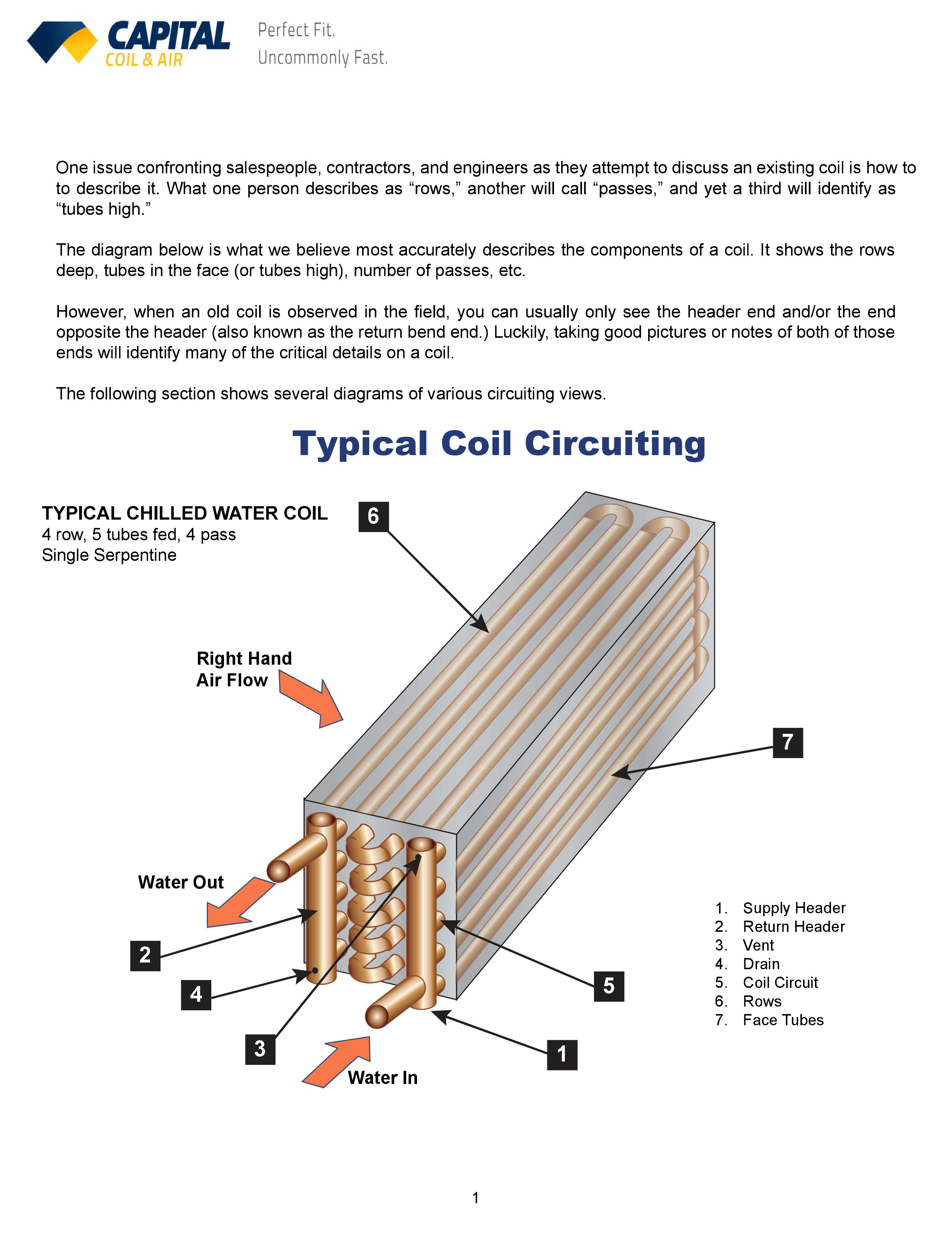
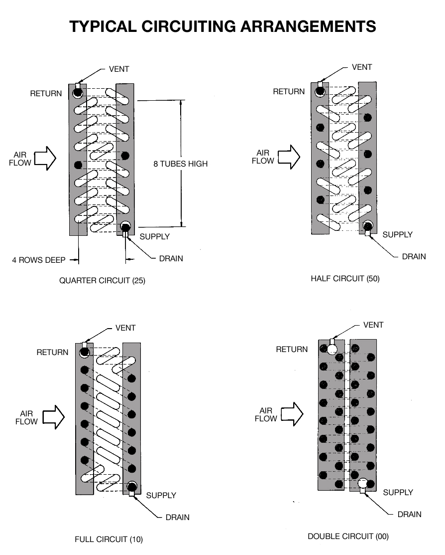
Chilled Water Cooling Coils Circuiting Made Easy
Wide fin spacing availability reduces the affect of frost build up on low temperature applications.
. With an air evaporator coil commonly used in low temperature supermar- velocity of 1 ms 35 of their total length was used in the quality kets applications. The fan-coil unit is frequently used in systems having variable capacities as described above and the evaporator of these units is sometimes provided with a plurality of refrigerant circuits groups of. Initial evaporator widthLD mm.
Evaporator Like the condensing unit evaporator coils also have performance curves Figure 2. The air flow over the evaporator coil is directed into one compartment at a time and is switched back and forth. Coil geometry fins rows height length etc.
1 A staggered pattern is more commonly used. Evaporator Coil Circuiting Options. Which are usually based on log mean enthalpy or log equivalent dry-bulb temperature difference.
Evaporator coil also called the evaporator core is the part of an air conditioning system where the refrigerant absorbs heat. The coil configuration selected consisted in a range 0751 while only 175 was used in the quality range of parallel-counter current combination of two circuits and the 0025. The selection process of the evaporators that operate in a system of refrigeration with CO2 is very similar to the selection of evaporators for ammonia.
Designed for use in comfort cooling process cooling and refrigeration Madok evaporator coils are proven for use with todays refrigerants. Refrigerant flowing through the coil tubes is controlled by a thermostatic-expansion valve. Pounders Marine Diesel Engines and Gas Turbines Tenth Edition 2021.
Unique interlaced circuiting options assure uniform refrigerant distribution over the entire face area of the coil. The evaporator curves are plotted as capacity tons versus SST and are based on two fixed factors. Design of Evaporator with CO2 Coolant.
Direct-expansion evaporator coils are used in low temperature refrigeration applications to cool and sometimes dehumidify air. Wide fin spacing availability reduces the affect of frost build up on low temperature applications. Evaporator coil circuit design Written By tienmccalebb33404 Friday April 8 2022 Add Comment Edit.
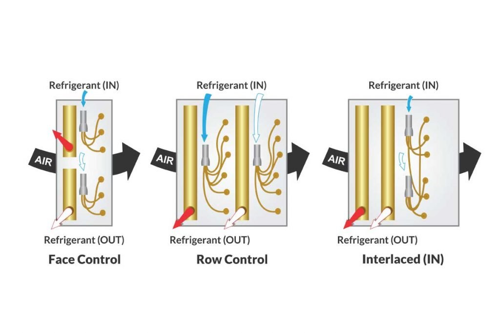
Focuses on Methods to design the cooling and dehumidifying coil or Direct Expansion evaporator coil. The heart of our air heat exchangers is the finned coil built up from a circuit of interconnected tube serpentines and hydrophilic anti-corrosive coated fins to increase the heat exchanging surface. Circuiting for face control and row control is also available as standard on a wide variety of coils.
Our proprietary circuiting provides for optimal system performance at minimal air-side and refrigerant pressure drops. The Product Evaporator circuit consists of an insulated pipe an evaporator valves a single wall pipe and sensors. In both methods the cooling coil is treated as a single zoneregion and hence the required surface area is determined 2.
A variety of load-split options provides the flexibility designers need to optimize the system not only at design conditions but. In a coil copper tubes are arranged parallel to one another either in staggered pattern or non-staggered pattern along the length L of the coil. Perfect for the Winter season months these wine and white nails are effortless to copy and look wonderful on clean short nails.
Unique interlaced circuiting options assure uniform refrigerant distribution over the entire face area of the coil. In the design of evaporator coils increasing refrigerant mass velocity can enhance the heat transfer of an evaporator coil. That is its where the cold air comes from.
EJ Model Type EJ Figure 4 coils come with interlaced circuiting. The heart of our air heat exchangers is the finned coil built up from a circuit of interconnected tube serpentines and hydrophilic anti-corrosive coated fins to increase the heat exchanging surface. The coil configuration selected consisted in a parallel-counter current combination of two circuits and the simultaneous presence of subcooled liquid phase change and superheated vapour.
Evaporator Coils Single dual or quad compressor circuits allow precise capacity control. A new modeling procedure for circuit design and performance prediction of evaporator coils using CO2 as refrigerant October 2010 Applied Energy 87102974-2983. However this will increases the pressure drop in the refrigerant side and performances of the.
Ambient design is 95F then the SST of the condensing unit must be 45F. For 12 inch tubes it is 125 inch. Single dual or quad compressor circuits allow precise capacity control.
Coil arrangement 0In-line 1Cross. By varying the combination of key design variables coil materials coil geometry casing design air units are very versatile heat exchangers with a great variety of. The heart of our air heat exchangers is the finned coil built up from a circuit of interconnected tube serpentines and hydrophilic anti-corrosive.
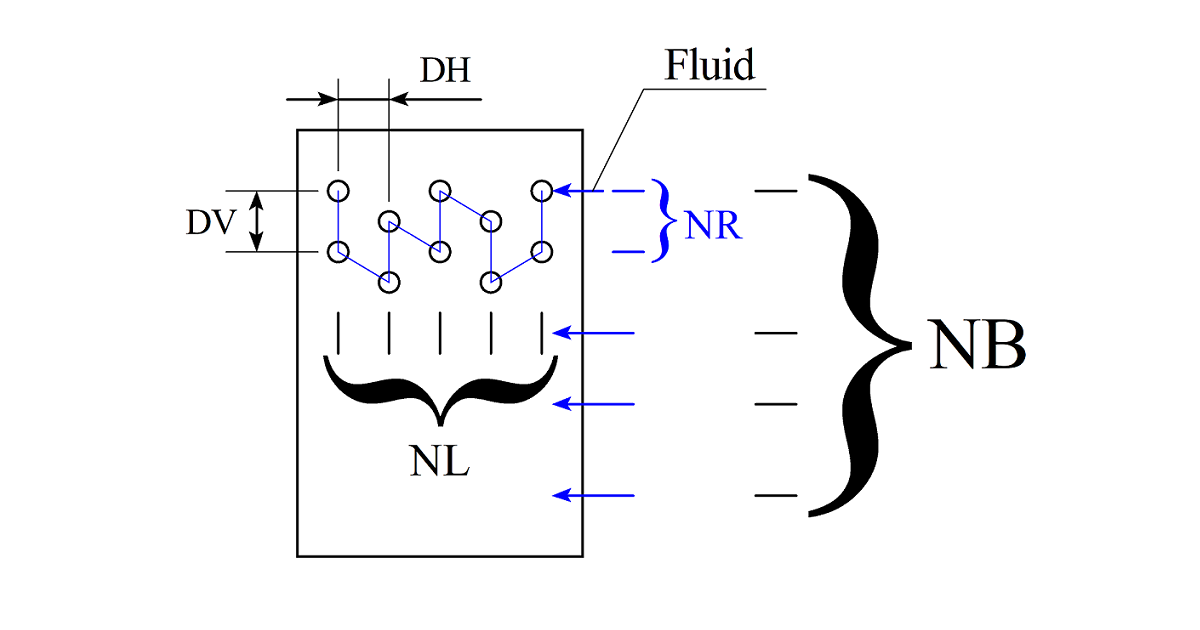
This form of capacity control. RowsNL along air flow. Circuits numberNB circuit per row.
Our proprietary circuiting provides for optimal system performance at minimal air-side and refrigerant pressure drops. Knowledge there is not an existing distributed simulation model for the study of tube circuitry of evaporator coils. The developed tool was then used to study a typical CO 2 evaporator coil commonly used in low temperature supermarkets applications.
Evaporator manufacturers commonly require the same data for both refrigerants and likewise performance and selection data will be displayed in the. Fin style0Straight 1Slot 2Triangle wave 3Sine wave Tube material-1See notes 0Copper 1Steel 2Aluminum Fin material-1See notes 0Aluminum 1Copper 2Steel. For use in central systems or duct applications.
Evaporator coil circuit design. Air passing across the fins is cooled as the refrigerant flowing through the tubes absorbs heat and is boiled evaporated. Direct Expansion Evaporator An Evaporator or Direct Expansion DX Coil works on the refrigeration effect cooling occurs when a fluid under.
The distributor is ideally mounted pointing up or down to minimize this liquidgas separation it blends these two fluids and evenly distributes this stream to. This manner of the cooling coil design could lead to an imprecise. To avoid this evaporator coils come with distributors.
The heat transfer capabilities of the evaporator coil. Evaporator Coils DCON. Bruce Nelson President Colmac Coil.
The fan-coil unit includes an evaporator which absorbs heat from air passing therethrough and a fan moving the air through the evaporator. Designed for use in comfort cooling process cooling and refrigeration Coilmaster evaporator coils are proven for use with all of todays refrigerants. Methods to design the cooling and dehumidifying coil either chilled water coil or Dx evaporator.
2

Numerical And Experimental Studies Of Refrigerant Circuitry Of Evaporator Coils Sciencedirect
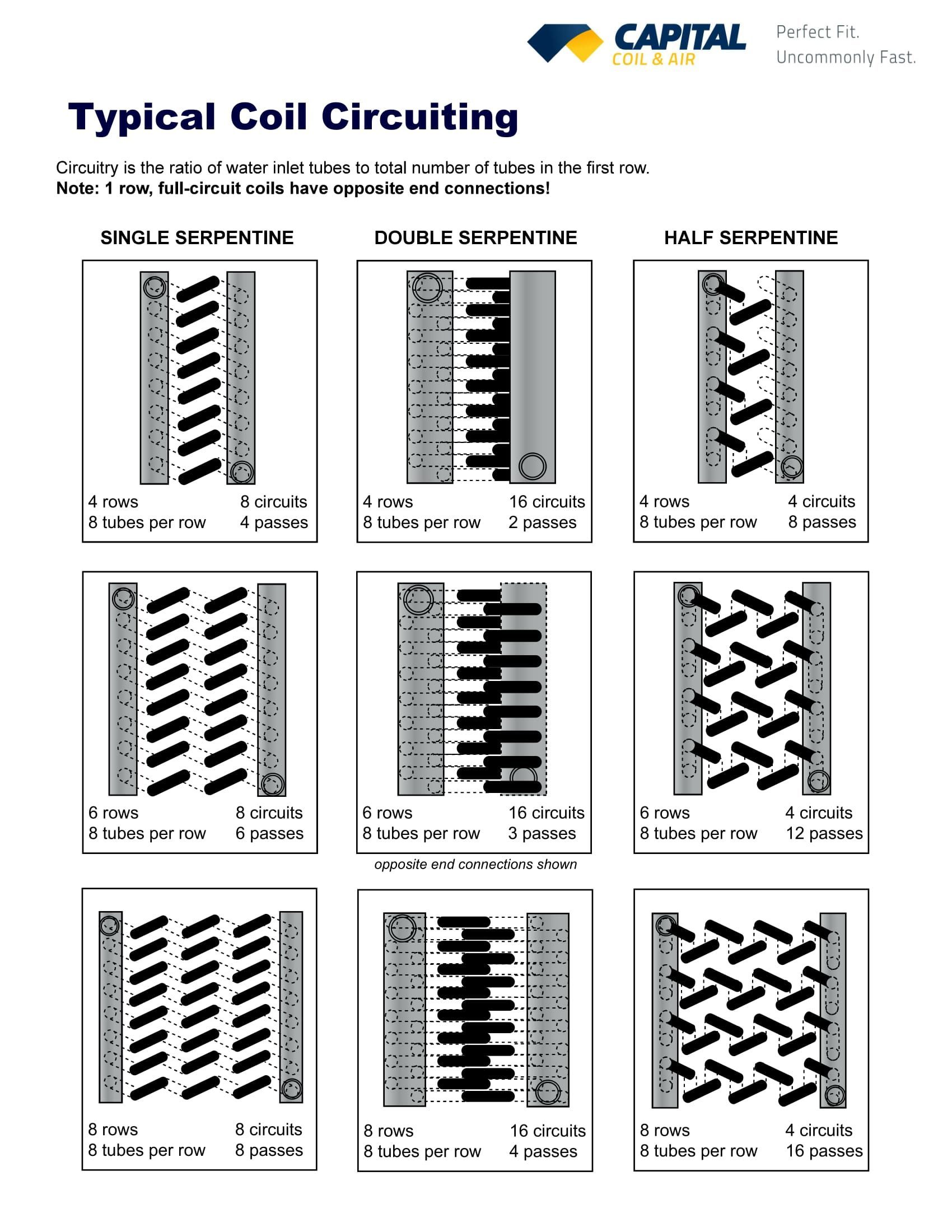
Chilled Water Cooling Coils Circuiting Made Easy

Evaporator Coil And Discretization Download Scientific Diagram

A New Modeling Procedure For Circuit Design And Performance Prediction Of Evaporator Coils Using Co2 As Refrigerant Sciencedirect
Understanding Coil Circuiting With A Simple Guide Campbell Sevey
Air Second Side Evaporator Design Calculation
The Benefits Of Intertwined Circuiting In Split Coils Fabtech
0 comments
Post a Comment